Understanding the Op Amp Non-Inverting Amplifier: A Comprehensive Guide
When it comes to amplifying signals in electronic circuits, the non-inverting amplifier stands out as a versatile and widely-used configuration. Designed using operational amplifiers (op-amps), this circuit configuration offers numerous advantages that make it a favorite among engineers and hobbyists alike. In this article, we will delve into the intricacies of the non-inverting amplifier, exploring its working principle, key components, and various applications.
How Does a Non-Inverting Amplifier Work?

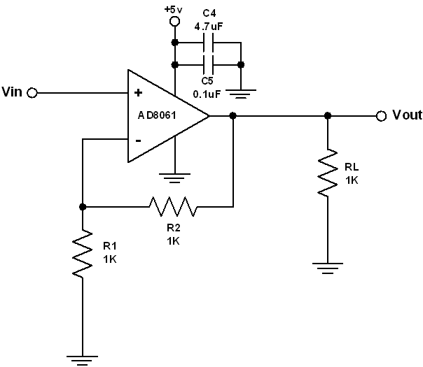
The non-inverting amplifier is a type of amplifier circuit that uses an op-amp in a non-inverting configuration. In this configuration, the input signal is applied to the non-inverting input terminal of the op-amp, while the inverting input terminal is connected to ground. The output signal is taken from the output terminal of the op-amp and is directly proportional to the input signal, with a gain determined by the external components connected to the op-amp.
When the input signal is applied to the non-inverting input terminal, the op-amp tries to maintain the voltage difference between its two input terminals at zero. This means that the voltage at the inverting input terminal will be equal to the voltage at the non-inverting input terminal. As a result, the output voltage will be amplified by a factor determined by the external components, typically resistors.
Key Components of a Non-Inverting Amplifier

Building a non-inverting amplifier requires a few essential components, including an op-amp, resistors, and a capacitor. Here’s a breakdown of each component’s role:
| Component | Description |
|---|---|
| Op-Amp | The operational amplifier is the heart of the non-inverting amplifier. It provides the amplification and buffering required for the circuit. |
| Resistors | Resistors are used to set the gain of the amplifier and to provide feedback to the inverting input terminal. |
| Capacitor | The capacitor is used to block any DC offset from the input signal and to filter out any noise or unwanted frequencies. |
One of the key advantages of the non-inverting amplifier is that it provides a high input impedance, which means that it does not load the input signal source. This makes it an ideal choice for amplifying signals from high-impedance sources, such as transducers or sensors.
Applications of Non-Inverting Amplifiers

Non-inverting amplifiers find applications in a wide range of electronic circuits. Some of the most common uses include:
-
Signal conditioning: Non-inverting amplifiers are often used to condition signals from sensors or transducers, such as temperature, pressure, or strain gauges.
-
Signal amplification: They are used to amplify low-level signals, such as those from microphones or photodiodes.
-
Filtering: Non-inverting amplifiers can be used to implement various filters, such as low-pass, high-pass, and band-pass filters.
-
Buffering: They can be used to provide a high-impedance buffer for a signal, which is useful when driving loads with high impedance.
Designing a Non-Inverting Amplifier
Designing a non-inverting amplifier involves selecting the appropriate components and determining the desired gain. Here are some key considerations:
-
Op-Amp Selection: Choose an op-amp with a wide bandwidth, low input offset voltage, and high input impedance to ensure optimal performance.
-
Resistor Selection: The resistors used to set the gain should have a low tolerance and high power rating to minimize errors and heat dissipation.
-
Capacitor Selection: The capacitor should have a low equivalent series resistance (ESR) and be suitable for the desired frequency range.
Once the components are selected, the gain of the amplifier can be calculated using the formula:
Gain = 1 + (Rf / Rin)
Where Rf is the feedback resistor and Rin is the input resistor


