
lm358 Op Amp Pin Diagram: A Comprehensive Guide
The LM358 is a widely used operational amplifier, known for its versatility and reliability. In this article, we will delve into the LM358 op amp pin diagram, exploring its various pins and their functions. Whether you are a beginner or an experienced electronics enthusiast, understanding the LM358 pin diagram is crucial for designing and implementing circuits effectively.
Pin Configuration

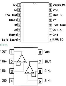
The LM358 op amp has eight pins, which are arranged in a standard dual-in-line package (DIP). The pin configuration is as follows:
| Pin Number | Pin Name | Description |
|---|---|---|
| 1 | VCC | Positive supply voltage |
| 2 | VEE | Negative supply voltage |
| 3 | Output 1 | Output of the first op amp |
| 4 | Inverting Input 1 | Inverting input of the first op amp |
| 5 | Non-Inverting Input 1 | Non-Inverting input of the first op amp |
| 6 | Output 2 | Output of the second op amp |
| 7 | Inverting Input 2 | Inverting input of the second op amp |
| 8 | Non-Inverting Input 2 | Non-Inverting input of the second op amp |
Now that we have a clear understanding of the pin configuration, let’s explore the functions of each pin in detail.
VCC (Pin 1)
Pin 1, labeled VCC, is the positive supply voltage pin. It provides the necessary voltage for the LM358 op amp to operate. The recommended supply voltage range for the LM358 is typically between 5V and 18V. Ensure that the supply voltage is within this range to avoid damaging the op amp.
VEE (Pin 2)
Pin 2, labeled VEE, is the negative supply voltage pin. Similar to VCC, it provides the necessary voltage for the LM358 op amp to operate. The recommended supply voltage range for VEE is typically between -5V and -18V. Ensure that the supply voltage is within this range to avoid damaging the op amp.
Output Pins (Pins 3 and 6)
Pins 3 and 6 are the output pins of the first and second op amps, respectively. These pins provide the amplified output signal from the respective op amp. The output signal can be either positive or negative, depending on the configuration of the circuit.
Inverting Input Pins (Pins 4 and 7)
Pins 4 and 7 are the inverting input pins of the first and second op amps, respectively. These pins are used to provide the input signal to the respective op amp. The input signal is applied to the inverting input, and the amplified output is obtained from the output pin.
Non-Inverting Input Pins (Pins 5 and 8)
Pins 5 and 8 are the non-inverting input pins of the first and second op amps, respectively. These pins are used to provide the input signal to the respective op amp. The input signal is applied to the non-inverting input, and the amplified output is obtained from the output pin.
Power Supply Decoupling
Proper power supply decoupling is essential for stable operation of the LM358 op amp. To achieve this, add


